This guide provides a structured process for preparing and verifying a CNC router before its first job. It covers machine alignment, spindle verification, tool calibration, and software checks to reduce errors and protect your investment.
- A structured setup process prevents scrap parts and machine damage.
- Verify machine alignment and spindle behavior before cutting production material.
- Document tool lengths and offsets for every job change.
- Run a test cycle on scrap material before starting production.
- Keep a printed checklist at the machine for every first run.
Why the First Run Matters More Than the Last
The first production run on a new cnc router sets the baseline for every job that follows. Errors introduced during setup, such as a misaligned table or an incorrect tool offset, multiply through every cut. A single bad offset can ruin an entire batch of parts. The goal here is not to rush. The goal is to build confidence in the machine before it touches valuable material.
A structured process also protects the machine. Spindles, bearings, and tool holders have tolerances. Exceeding those tolerances during a test cut can cause permanent damage. This checklist works for both new machines and used machines that have just arrived from a vendor. It is designed for professional buyers and engineers who need a repeatable standard.
Verify Machine Alignment and Table Condition
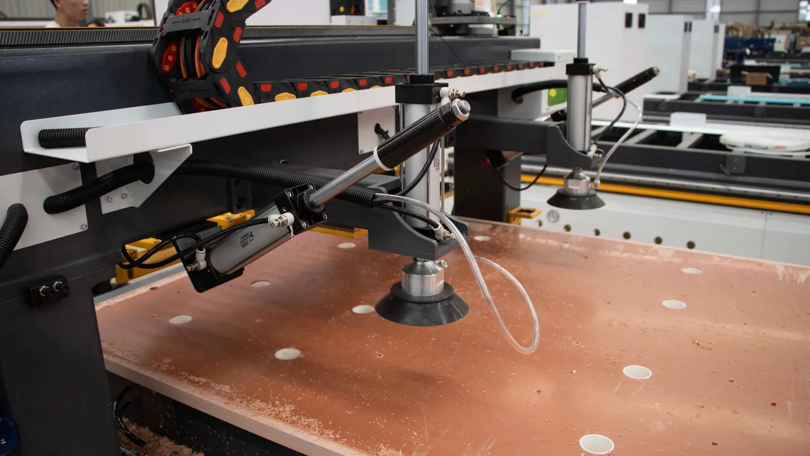
Start with the physical machine. Before loading any material, check the table surface. Look for scratches, gouges, or debris that can affect part flatness. A level table is the foundation of accurate machining. Use a precision level or a dial indicator to check the table across all four directions.
Check the linear guides. Move the table slowly in all axes. Listen for grinding or catching. Feel for rough spots. If a guide feels gritty, stop. Dirty guides can cause positioning errors that show up as inconsistent part dimensions. Clean the rails and apply the recommended lubricant.
Verify the machine frame. Look for loose bolts or cracked welds. Tighten any fasteners that have shifted. Vibration from a loose frame can cause tool chatter, which damages edges and reduces tool life. A machine that vibrates during a light cut will vibrate worse during a heavy cut.
Check Spindle Health and Mounting
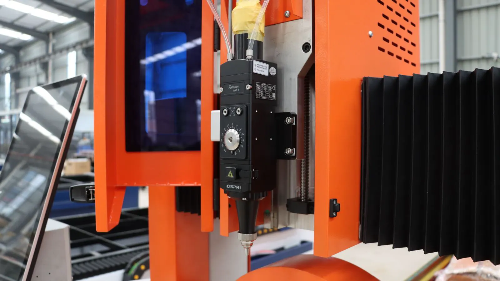
The spindle is the heart of the machine. Before the first run, inspect the spindle tool holder. Look for nicks or burrs on the shank. A damaged shank can cause imbalance. Imbalance creates vibration and noise at high speeds. If the shank is damaged, replace the holder. Do not file it down unless you have the proper tooling and tolerance knowledge.
Spin the spindle at low speed. Listen for noise. A healthy spindle runs smoothly. If you hear a whine or a rumble, stop. Do not force it. A bad bearing will not get better with time. It will get worse.
Check the spindle mounting. Ensure the spindle is seated fully in the housing. A partially seated spindle will run out of true. The tool axis will not match the intended axis. This causes parts to be off by a small amount, which compounds in multi-part assemblies.
Calibrate Tool Lengths and Offsets
Tool offsets are the most common source of first-run errors. Every tool has a length. Every tool has a diameter. The machine controller needs to know both. Do not assume the tool length is the same as the previous tool. Even tools from the same manufacturer can vary.
Measure every tool with a digital caliper or a tool setter. Record the actual length and diameter. Enter these values into the machine controller. If the machine has a tool setter, use it. If it does not, measure manually and enter the data.
Create a tool list. Include the tool number, name, length, diameter, and speed. Keep this list at the machine. When the next job arrives, the operator should be able to find the tool data in seconds. If the data is in a spreadsheet on an office computer, the operator will skip it. Put it where the work happens.
Review CAM Software and Post-Processor
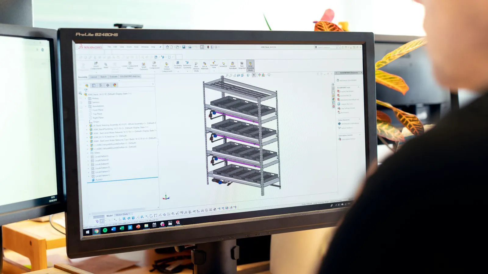
The cnc machining process starts in the software. Before the machine sees a file, the computer must generate it. Check the CAM program. Verify the stock size. Verify the tool paths. Look for collisions.
Run a simulation. A simulation is not a guarantee, but it catches obvious errors. Look for tool paths that start outside the stock. Look for rapid moves that cross the table. Look for tool changes that happen when the tool is not accessible.
Check the post-processor. The post-processor translates CAM code into machine language. If the post-processor is wrong, the machine will do something unexpected. Verify the post-processor matches the machine model. If you changed the machine, you may need a different post-processor.
Run a Test Cycle on Scrap Material
Never run a production job on the first attempt. Cut a piece of scrap material. Use the same tooling and the same speed as the production job. If the production job uses hardwood, use hardwood scrap. If it uses MDF, use MDF scrap. Different materials cut differently.
Watch the first few minutes. Look for tool chatter. Listen for changes in spindle load. Check the surface finish. If the finish is rough, adjust the feed rate or the speed. If the edges are burnt, reduce the speed. If the cuts are deep, reduce the depth of cut.
Measure the test part. Use a caliper or a micrometer. Check the dimensions against the drawing. If the part is off, find the cause. It may be a tool offset. It may be a machine alignment issue. It may be a software error. Fix the root cause. Do not just adjust the offset to make the part fit. That hides the problem.
Document the Setup for the Next Run
A setup is not complete until it is recorded. Write down what you did. Note the tool lengths you measured. Note the speeds and feeds you used. Note any adjustments you made. Keep this record with the job file.
The next operator should not have to guess. They should be able to pick up the record and follow the same process. This is how you build consistency. It is also how you build confidence. When the first run is documented, the second run is faster and less risky.
Table: Key Checks for First Production Run
| Check | What to Look For | Action if Failed |
|---|---|---|
| Table Level | Surface is flat and level | Adjust feet or machine base |
| Spindle Noise | Smooth sound at low speed | Stop and inspect bearings |
| Tool Offset | Matches measured length | Re-measure and re-enter |
| Tool Path | No collisions in simulation | Adjust CAM program |
| Test Part | Dimensions within tolerance | Find root cause before production |
Common Red Flags to Watch For
Some issues are easy to miss. Here are the red flags that cause the most damage.
- Chatter marks on the test cut. This means the tool is not rigid. Check the tool holder. Check the tool. Check the feed rate.
- Spindle temperature rising fast. This can mean a bad bearing. It can also mean the tool is not sharp. Check both.
- Part dimensions shift during the run. This means the machine is drifting. Check the alignment. Check the thermal expansion.
- Tool breaks during the first cut. This means the tool is not suited for the material. Check the material hardness. Check the tool type.
- Software crash during import. This means the file is corrupted or the post-processor is wrong. Check the file. Check the post-processor.
Final Verification Before Production
Before you load the production material, do a final walk-around. Check that the correct tool is in the holder. Check that the correct program is loaded. Check that the material is clamped securely. Check that the emergency stop is accessible.
Load the material. Align it. Run a single pass at a reduced depth of cut. If that looks correct, run the full job. If the first pass looks bad, stop. Do not push through. A bad first pass is cheaper than a bad production run.
The first run is a test. Treat it as such. The machine is not ready for production until the test passes. When the test passes, you have a baseline. You can now run the first production run with confidence.
Frequently asked questions
How long should a cnc machining setup take?
A thorough setup can take several hours. The time depends on the number of tools and the complexity of the job. Rushing setup is the most common way to ruin parts.
Do I need to check the machine alignment for every job?
Yes. Check the alignment before every job. The machine can shift during transport or during heavy cuts. A small shift can ruin a batch of parts.
Can I use the tool length from the previous job?
No. Tool lengths vary. Even tools from the same box can be different. Measure every tool for every job.
What should I do if the test part is out of tolerance?
Stop. Find the root cause. Check the tool offset. Check the machine alignment. Check the software. Do not adjust the offset to force the part to fit.
Is a simulation enough to catch errors?
No. A simulation catches obvious errors, but it does not catch everything. Always run a test cycle on scrap material before production.