This guide explains how to match CAD, CAM, and controller software with your specific router hardware. It defines the stack, shows how each layer affects machine control and file export, and provides a worked example to help you verify compatibility before purchase or upgrade.
- A working system requires three aligned layers: CAD for design, CAM for toolpaths, and a controller for machine execution.
- The controller determines the native file format and communication method, which dictates your CAM software choice.
- Always verify file export options and communication protocols against the specific router hardware you own or plan to buy.
- Mismatches between software and hardware cause wasted time, failed jobs, and costly troubleshooting.
- A simple export-to-g-code test is the fastest way to confirm a software stack works with your machine.
What the Software Stack Actually Means
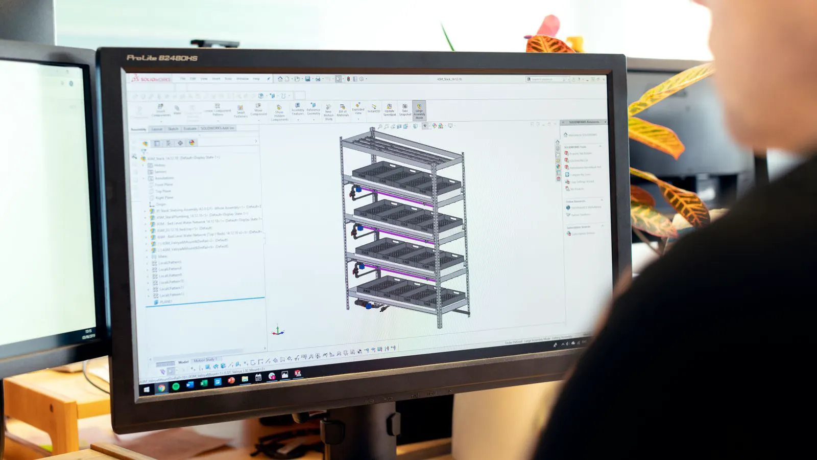
A cnc router does not run on one piece of cnc software. It runs on a stack. The stack has three distinct layers. The top layer is CAD, where you draw the part. The middle layer is CAM, where you turn the drawing into toolpaths. The bottom layer is the controller, which is the brain inside the router that executes those toolpaths.
These layers speak different languages. CAD files describe geometry. CAM files describe motion. Controller files describe machine actions. If the stack is misaligned, the job fails. If it is aligned, the machine runs predictably.
This guide focuses on compatibility. It assumes you already have a router or are selecting one. The goal is to determine which software works with that specific hardware.
How the Router Controller Dictates Your Options
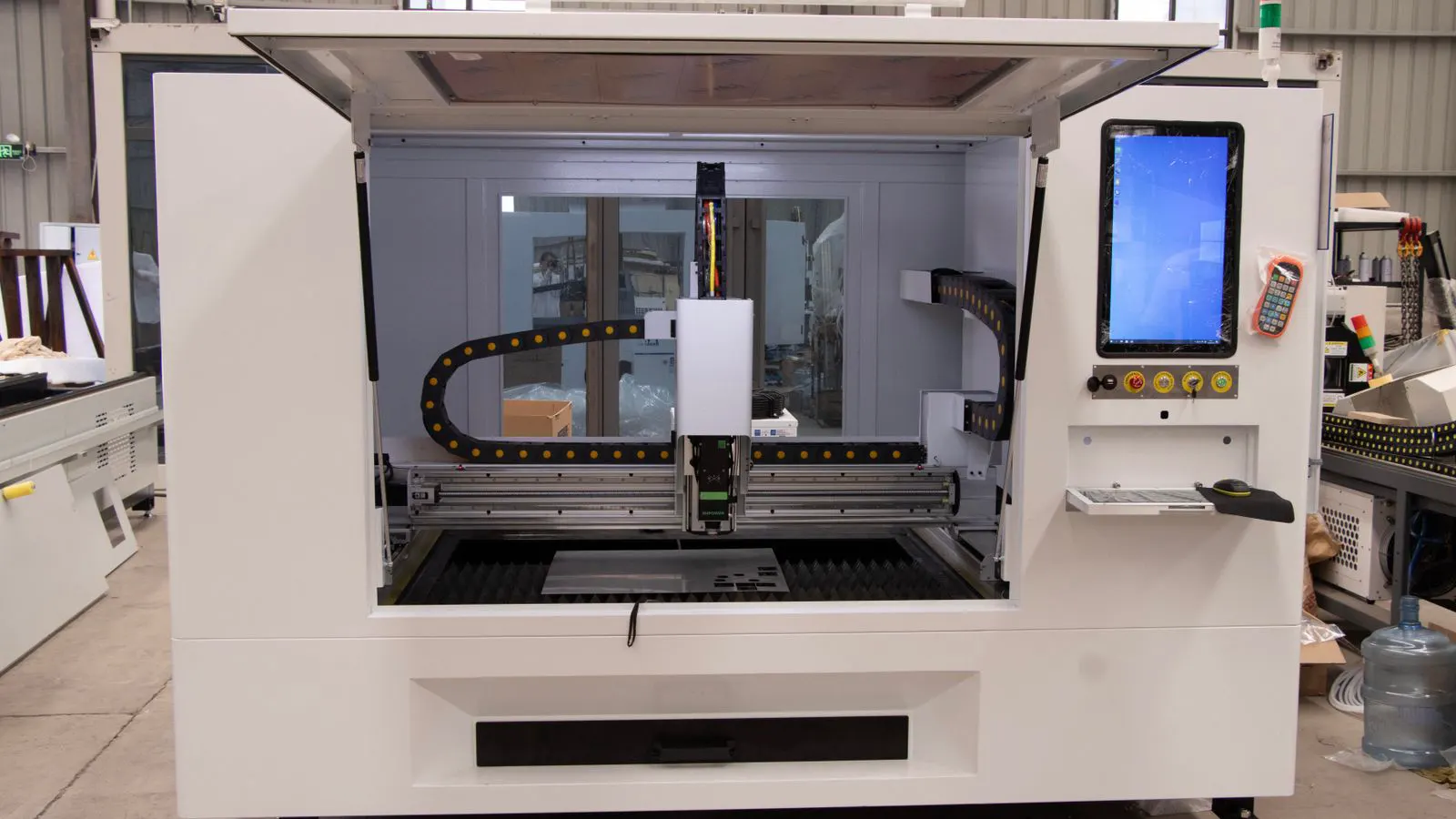
The controller is the most restrictive layer. It is installed in the machine. You cannot change it without major modification. The controller defines what input it accepts and how it communicates.
Most woodworking cnc routers use one of two common controller families. The first family accepts G-code files directly. The second family accepts a proprietary file format from a specific CAM package. Some controllers accept both. Some accept neither, requiring an intermediate conversion step.
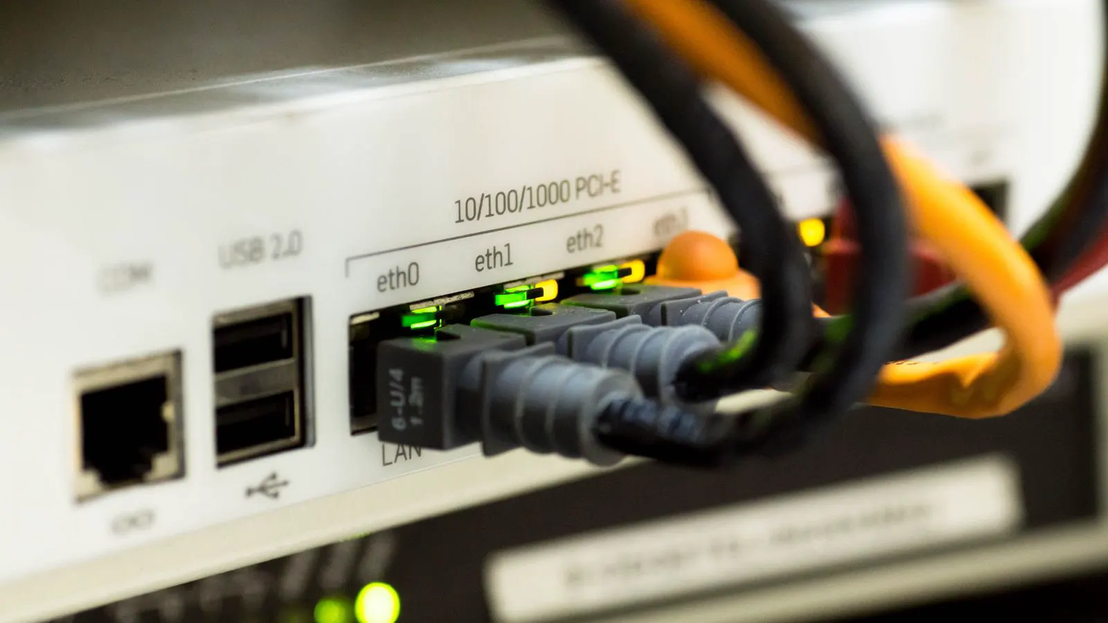
The communication method matters as well. Some controllers use USB. Some use serial ports. Some use Ethernet. Some use wireless. The connection type affects how you move files from your computer to the machine.
When you buy a router, the controller is part of the hardware specification. It determines which CAM software you can use. It also affects how you set up the machine and how you manage updates.
How CAM Software Bridges Design and Machine
CAM software takes your CAD geometry and converts it into toolpaths. The toolpath defines the speed, depth, and direction of the cutter. It also defines which tool to use at each stage.
The output of CAM is a post-processed file. This file is often G-code, but it can be a proprietary format. The post-processor is critical. It must match your router controller. If the post-processor is wrong, the machine may run the wrong tool, at the wrong speed, or in the wrong order.
CAM software also handles tool libraries. You define your bits in the software. The software uses that data to calculate toolpaths. If the tool library is inaccurate, the cut will be wrong.
The CAM package must support the file formats your CAD system exports. It must also support the post-processors your controller requires. This is where most compatibility problems arise.
How CAD Feeds the CAM Layer
CAD software creates the geometry. Common CAD formats in woodworking include DXF, DWG, SVG, STEP, and native formats specific to the CAD package.
The CAD software must export in a format that your CAM software can read. Not all CAM packages read all CAD formats. Some read DXF and SVG. Some read STEP and IGES. Some read only their own native format.
The quality of the geometry matters. A CAD model with open loops, overlapping lines, or wrong units will fail in CAM. The CAD file must be clean before it reaches the CAM stage.
In a typical workflow, the CAD file is exported, imported into CAM, and then processed. If any step fails, the job stops. The CAD layer is upstream. Problems here are harder to detect than problems in the CAM layer.
How to Verify Compatibility Before You Buy
Verification is a practical process. It takes minutes. It prevents expensive mistakes.
First, identify the controller in your router. Check the machine manual, the controller label, or the seller’s specification sheet. If the controller is not specified, ask the seller directly.
Second, identify the CAM software you plan to use. Check the software documentation for supported file formats and post-processors.
Third, check the controller’s input requirements. Does it accept G-code? Does it accept a proprietary format? Does it require a specific communication protocol?
Fourth, run a test. Export a simple part from CAD. Process it in CAM. Post-processed the toolpath to your controller format. Load the file onto the router. Run a dry cut or a test cut on scrap wood.
This test confirms the entire stack. If any layer fails, you know where the problem is before you start real work.
A Worked Example in Plain Words
Let’s walk through a scenario. You have a woodworking cnc router. The router uses a controller that accepts G-code files over USB. You plan to design parts in a CAD package that exports DXF files. You plan to use a CAM package that reads DXF and has a G-code post-processor.
Step one: You draw a cutting board in CAD. The board is 300 by 200 millimeters. You export it as DXF.
Step two: You import the DXF into CAM. You set your tool library. You select a 6 millimeter end mill. You set the feed rate and spindle speed. You define the cut depth.
Step three: You run the toolpath simulation. The simulation looks correct. The cutter follows the outline. The internal cut is where needed.
Step four: You post-process the toolpath. You select the G-code post-processor that matches your router controller. The software generates a G-code file.
Step five: You copy the G-code file to a USB drive. You plug the USB drive into the router controller. You load the file. You set the work zero. You run the job.
If any step fails, you know exactly where. If the CAD file does not export as DXF, the CAD layer is the problem. If the CAM software does not read DXF, the CAM layer is the problem. If the G-code file does not load on the controller, the controller layer is the problem.
This is the point of verification. You isolate the failure before you waste a sheet of wood.
Common Compatibility Mistakes to Avoid
The first mistake is assuming all G-code is the same. It is not. Different controllers interpret G-code differently. Some expect certain lines. Some reject others. The post-processor must match the controller.
The second mistake is ignoring the communication protocol. A G-code file may be correct, but if the controller expects serial input and you use USB, the file will not load. Check the port type.
The third mistake is skipping the tool library setup. If the tool library in CAM does not match the physical tools on the machine, the cut will be wrong. The software does not know what is in your tool holder.
The fourth mistake is using outdated software. Older CAM versions may not support newer CAD formats. Older controllers may not support newer communication standards. Keep your stack current.
The fifth mistake is not reading the manual. The router manual and the CAM manual are the primary sources of compatibility information. They are more accurate than forum posts or vendor claims.
How This Affects Sourcing Decisions
When you source a router, the software stack is part of the machine. It affects which CAM packages you can use. It affects which CAD formats you can import. It affects how you move files to the machine.
If you already use a specific CAM package, choose a router whose controller supports that package. If you plan to switch CAM packages, choose a router whose controller supports the new package.
If you are buying used, verify the controller. Ask the seller for the controller model and firmware version. Ask for a sample G-code file that ran successfully on the machine.
If you are buying new, request the controller specification in writing. Confirm the file format, communication protocol, and supported CAM packages before you sign the order.
This is not a small detail. It is the difference between a machine that runs and a machine that sits idle.
Summary Table: Layer, Function, and Compatibility Check
| Layer | Function | Key Compatibility Check |
|---|---|---|
| CAD | Creates geometry | Export format must be readable by CAM |
| CAM | Generates toolpaths | Post-processor must match controller |
| Controller | Executes toolpaths | Accepts the correct file format and protocol |
| Communication | Moves files to machine | Port type must match controller input |
This table shows the four points where failure occurs. Each point is a place to verify before you start work.
Final Verification Steps
Before you run a production job, run a short checklist.
- Confirm the CAD file exports in the format your CAM software reads.
- Confirm the CAM software supports the post-processor for your controller.
- Confirm the controller accepts the file format and communication protocol.
- Run a test cut on scrap material.
- Inspect the cut for accuracy and surface finish.
This checklist takes minutes. It prevents hours of troubleshooting. It protects your machine, your tools, and your time.
The cnc software stack is not a single product. It is a system. Each layer must work with the others. When the stack is aligned, the router performs as expected. When it is misaligned, nothing works.
Check the layers. Verify the formats. Test the stack. Your router will run clean.
Frequently asked questions
Can I use any CAM software with any cnc router?
No. The router controller determines which file formats and communication protocols it accepts. Your CAM software must match those requirements.
What is the most common file format for woodworking cnc routers?
G-code is the most common format for toolpath files. However, some controllers use proprietary formats, so always check your specific router's documentation.
How do I know if my CAD file is compatible with my CAM software?
Check the CAM software's documentation for supported CAD file formats. Then export a test file from your CAD package and confirm it imports correctly into CAM.
Do I need the same CAD and CAM software from the same vendor?
No. You can mix and match as long as the CAD file exports in a format the CAM software reads, and the CAM software posts to a format the controller accepts.
What should I ask a seller about software compatibility?
Ask for the controller model, the accepted file format, the communication protocol, and a sample toolpath file that ran successfully on the machine.